Tool centralization and correction of caliper lengths
Because of decentralization of the six-arm tool, distances between opposite pads (P1-P4, P2-P5, and P3-P6) give lengths of chords of a circle instead of borehole diameter, even in an intact well, as shown in the image below.
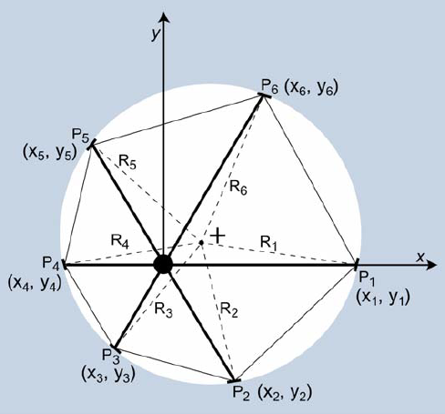
Schematic image: distances between opposite pads give lengths of chords of a circle instead of borehole diameter. P = position of pads, R = corrected length of the arms. click to enlarge
Therefore, a mathematical centralization procedure must be performed. For simplicity, let the tool axis be located in the center of the Cartesian coordinate system and the direction of the first arm coincide with the positive x-axis (illustrated in the image above). The tool pads are then described in terms of their polar coordinates as follows:

|

|

|

|

|

|

|

|

|

|

|

|
This centralization procedure is based on the assumption that the center of weight of the hexagon with vertices at the six tool pads is close to the center of the circular well. Coordinates of the center of the hexagon (x0, y0) are given by the mean of the six coordinates:

|

|
The corrected length of each arm is the distance from the center of the hexagon to a corresponding pad:

|

|

|

|

|

|
The sums of corrected lengths of opposite arms are an approximate measure of the borehole diameter (instead of chords P1 + P4, P2 + P5, P3 + P6) and are called “calipers,” C1, C2, C3.

|

|

|
Maximum, minimum and intermediate caliper are calculated from C1, C2, C3 (Cmax=maximum(C1, C2, C3), …). In contrast to that, the calipers which are directly calculated from the chords are denoted with a prime (C'): C'max=maximum(P1+P4, P2+P5, P3+P6).